|
|
Tech Articles
Contents
TPS Adjustment
IAC
Cleaning & Adjustment
Base Idle Reset
Timing Belt Replacement
Timing Adjustment
Timing Adjustment/Reset
w/o Timing Cover
Manual Cooling Fan Switch
Wiring
91-93 Oil Pan Removal
79-90 Oil Pan Removal
A/F Gauge Install
VAM Testing Procedure
Future Articles
Throttle Position Sensor (TPS)
Adjustment
Symptoms: high idle, won't idle, dies when throttle is lifted when slowing
down
These
sensors show as no longer available at most parts stores but if you
choose the right application, you can still get them from us here:
2.3 Turbo Adjustable TPS
1. First bring the
engine up to normal operating temperature.
2. Turn the
engine off and unplug the Idle Air Control (IAC). This is located on the
backside of the Throttle Body near the firewall. This device is a round
cylinder approximately 5 inches long with a (2) bolt flange and 3 wire
male / female plug connector (see pic).
3. Start engine
and using a screwdriver adjust the base idle to 700 – 800 RPM using the
screw on the throttle body (see pic)
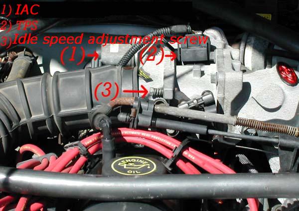
4. Locate the
Throttle Position Sensor (TPS) on the Throttle Body. This is also located
on the backside of the Throttle Body near the firewall. This is a black
plastic device with (2) screws that allows adjustment and (3) wire male /
female connector (see pic above). Connect the voltmeter to the TPS and
ground. The wire should be either black with a green stripe or green with
a black stripe.
5. Using the
small Phillips screwdriver adjust the TPS output voltage to approximately
1.0 volts. Most turbo tuners find that setting your voltage to around .90
- .95 volts works best. I set mine around .94 volts.
6. Turn off the
engine.
7. With the
engine off and the voltmeter still connected move the throttle linkage
slowly from idle position to wide open and back to idle, look for a steady
increase and then decrease in voltage without any voids or dead spots. Any
voids or dead spots would indicate a faulty TPS. If you find a dead
spot you need to replace the TPS.
8. Plug in the
IAC.
9. Start the
engine. The engine’s idle speed should settle in around 1000 RPM. If
it settles higher than this, adjust the screw until idle is at 1000 RPM.
10. Go for a
test drive and enjoy the smooth idle.
Idle Air Sensor (IAC)
Cleaning & Adjustment
Symptoms: wandering idle, hanging high idle, idle problems when at operating
temperature.
Note: This is normally done in conjunction with the TPS adjustment above
to get the idle set properly.
1. Bring
engine up to operating temperature. This is located on the backside
of the Throttle Body near the firewall. This device is a round cylinder
approximately 5 inches long with a (2) bolt flange and 3 wire male /
female plug connector (see pic above).
2.
Turn the engine off
and unplug the Idle Air Control.
3. Remove 2 screws near the plug.
4. Remove two bolts holding the
cylinder on the throttle body.
5. Push "piston" inside canister in and out to see if it moves freely.
6. Spray carb cleaner into piston area and move piston to clear out carbon
deposits, repeat.
7. Blow out the excess cleaner and carbon deposits with compressed air
(your mouth will suffice if it must)
8. Install
cylinder with bolts.
9. Install plug with screws.
10. Start car, if it won't stay running then turn the idle adjustment
screw on the throttle body towards the driver's side until it will stay
running.
11. Turn the idle screw until it reaches 600-700rpm at idle.
12. Plug in
3 wire connector, if the IAC is functioning the engine should
smooth out and the idle should jump up to 1000-1500 RPM.
13. Turn the idle screw until it idles at 1000rpm. Rev engine a few
times to be sure it stays at 1000rpm at idle.
14. Remove tools, shut hood, and go for a drive.
Base Idle Reset
1.
Bring car up to operating temperature.
2. Unplug the
IAC.
3. With the IAC
disconnected and the idle adjusted to 750 RPM, shut off the engine and
plug the IAC back in.
4. Unplug the
battery cable and let it sit for 30 minutes.
5. Hook the
battery back up and start the engine.
6. Let the car
idle for 10 minutes and then go for a drive. It may take up to 75
miles for the computer to fully reset and learn the new settings.
Timing Belt Replacement
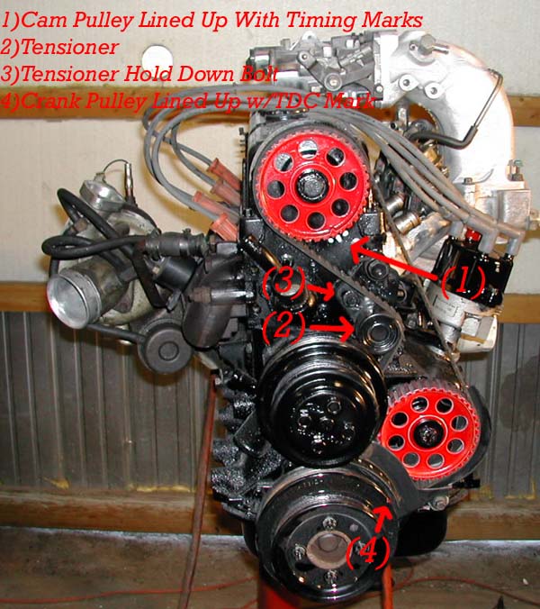
Use the pics below to
reference what is stated here.
Removing the belt:
1.
Set the engine at Top
Dead Center (TDC) on compression stroke (crank pulley mark should be at TC
on the timing cover and the cam notch should be visible through the little
hole in the timing cover, see pic below).
2.
Remove the timing
belt cover. This involves removes anything in its way (pulleys, etc.).
This is a real pain to remove if it's not already broke. Take your
time and remove whatever seems to be holding it on.
3.
Mark the cam, crank,
and auxiliary pulleys "straight up" with some chalk or a marker. Make
sure that they stay "straight up" throughout this procedure. If they
get moved slightly, move them back.
4.
Find the tensioner
hold down bolt (see pic below) that's located next to the tensioner pulley
and loosen it enough to move the tensioner.
5.
Put a breaker bar between the tensioner and the crank pulley or between
the tensioner and water pump and push upwards to release tension on the
tensioner pulley. It takes a good bit of force to release the
pressure.
6.
Once you release the
pressure, hold the breaker bar and tighten the hold down bolt in it's new
"loose" location.
7.
Now you can remove
the belt. The easiest way is to just cut the belt and pull it out of
the way.
Installing
the new belt:
1. Wiggle
your belt back onto the pulleys. It may take some work to get it
around the crank timing belt pulley.
2.
Once the belt is
routed properly, remove all the tension from the DRIVER'S SIDE of the
belt. You want to get it as tight as possible on that side.
Make sure the belt teeth are lined up with the cam and crank pulley teeth
and all the slack is removed. You may have to VERY carefully move
the cam back a little bit to get the belt on, then move it back again to
tighten it all the way up. The tension on the other side doesn't
matter because the tensioner will take care of it when it's released.
3.
Check to make sure all marks you put on the pulleys are still positioned
"straight up".
4.
Release the tensioner
hold down bolt slightly and the tensioner will spring back into place.
5.
Put the breaker bar
back under the tensioner and hold enough pressure on it so there is
approximately 1/2" of slack in the belt on the driver's side.
6.
Once the correct
slack is obtained tighten the hold down bolt.
7.
At this point the
hard work is complete and you can now install everything in the reverse
order of how you removed it. Once that is complete, check to make
sure everything is correct and then start the car.
8.
Now you can proceed
to the Timing Adjustment below to set the timing to factory specs.
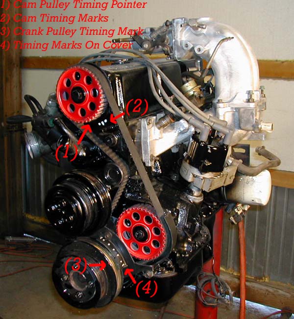
Timing Adjustment
Follow these steps after completing timing belt install above or to set
timing to factory specs.
1.
Make sure you have the
timing belt cover installed (or at least the lower part around the
crankshaft pulley)
2.
Put timing light connector on #1 spark plug wire (nearest the front of
the car).
3.
Locate distributor hold down bolt and use a 12+" long 3/8" extension
and ratchet to loosen bolt. You only need to turn it a small
amount...just enough to release the tension.
4.
Unplug spout connector (small gray plug located within 6" of ignition
module that's bolted to the side of the distributor, the plug is located
within the ignition harness).
5. Make sure the timing light wires are out of the way of the engine
pulleys.
6. Start car.
7.
Point timing light towards the timing marks near the crankshaft pulley
on the timing cover.
8.
Locate the 10* BTDC mark on
the cover (factory setting) and turn the distributor slightly until the
"notch" in the pulley lines up with the desired timing (10*BTDC).
9.
Once the desired timing marks are lined up tighten the distributor hold
down bolt.
10.
Recheck timing to make sure the distributor didn't move when
tightening it down.
11.
Plug in Spout Connector and check timing, it should be advanced to
20 degrees or more now and move with rpms.
12.
Shut off engine, remove tools, close hood, and enjoy your new found
power.
Timing Adjustment/Reset
Without Timing Cover
Follow these steps if you don't have a timing belt cover and have thrown
the timing belt.
1.
Turn over the auxiliary
pulley if you can't see the timing mark that is on it. Sometimes the
aux pulley is reversed so that you can't see the timing mark that is on
it. The aux pulley is the same part as the cam pulley but everyone
that I have seen is turned over so that you can't see the timing mark.
2.
Turn the crank so that the
crank bolt, the TDC mark (on the compression stroke, not the exhaust
stroke), the auxiliary pulley bolt and the auxiliary pulley
timing mark form a straight line. The crank and aux pulley timing mark's
will not be next to each other but both will be pointed in a straight line
with the crank and auxiliary bolts towards the driver's fender.
3.
If you can't or haven't
turned over the auxiliary pulley just check to see that the rotor button
is pointing to the Four O'clock position
4.
Check the distributor. The
rotor should be at about the 4 o'clock position, if not move it now.
The crank and auxillary pulley and distributor are now aligned.
5.
Now put a straightedge or piece of wire in a straight line between the cam
pulley bolt and the auxillary pulley bolt.
6.
Turn the cam until it's timing mark is in line with this straight line.
7.
You're done. If you
are stuck somewhere this method will set the timing to Zero Degrees BTDC.
This is an emergency method only. It will get you home however. Once
you get home, adjust timing to 10* BTDC as shown above.
Manual Cooling Fan Switch
Wiring
Reasons for doing this: Fan doesn't work, allowing manual control of fan
(useful for pulling air through the IC when getting ready to race)
Run a heavy (10-12 gauge)
wire from the positive side of the fan through the firewall and to the
location you choose to mount the switch. Attach it to the positive
(+) side of the switch. Leave the negative (-) wire on the fan in
its stock location. Run a black wire from the negative (-) side of
the switch to a screw on the fuse panel frame. Run a small wire from
the (acc) plug on the switch to a spot on the fuse panel that comes on
with the key at the accessory (acc) position or the on position and shuts
off when the key is off. Turn the key to (acc) and flip the switch
to (On). Make sure the fan is operating. Turn the key to (Ign)
and make sure the fan is operating again. Flip the fan switch to
(Off) and see that the fan quits. If it worked as described then you
are done. If not, start tracing your work to figure out what you
screwed up.
91-93 Oil Pan Removal
To remove the oil pan
"in-chassis", follow these steps:
1.
Raise the car and place it on jack stands.
2.
Drain the oil.
3.
Remove the motor-mount bolts
and raise the motor as high as you can with a winch. Support it
under the crank pulley with a stand and a block of wood.
4.
Disconnect the steering shaft from the rack and pinion at the "rag"
joint and tap it upward and out of the way (it's telescopic to prevent you
from being impaled).
5.
Take all 8 bolts out that attach the front crossmember to the "frame"
(it won't fall - trust me). The bolts have a torx head, but you can use a
standard 6-point socket.
6.
Remove the four bolts holding the anti-sway bar brackets to the frame
and let the bar hang.
7.
Drive a wooden wedge between the rear of the crossmember and one side
of the frame (this will not only lower it, as it compresses the suspension
springs which is what's holding it up, but it will usually slide forward
as well.
8.
Remove the starter.
9.
Drop the pan down low enough to disconnect the oil pump from the block,
allowing it to drop in the pan (you'll need an 8mm 12-pt socket for the
pump body and a 14mm for the pickup support.
10.
Slide the pan out the back.
79-90 Oil Pan Removal
To remove the oil pan
"in-chassis", follow these steps:
1.
Raise the car and place it on jack stands.
2.
Drain the oil.
3.
Remove the motor-mount bolts
and raise the motor as high as you can with a winch. Support it
under the crank pulley with a stand and a block of wood.
4.
Disconnect the steering shaft from the rack and pinion at the "rag"
joint and tap it upward and out of the way (it's telescopic to prevent you
from being impaled).
5.
Remove the four bolts
holding the anti-sway bar brackets to the frame and let the bar hang.
6.
Remove the starter.
7.
Drop the pan down low enough
to disconnect the oil pump from the block, allowing it to drop in the pan
(you'll need an 8mm 12-pt socket for the pump body and a 14mm for the
pickup support.
8.
Slide the pan out the back.
Compression Test
Be sure to bring the engine up to full operating temperature before
proceeding.
1.
First, take an air
compressor or shop vac and clean the area around each spark plug recess
BEFORE removing the plugs in order to prevent any dirt/sand from dropping
into the cylinder.
2.
If turbocharged, remove the intercooler. Be sure to cover the turbo inlet
hole with a towel or cup.
3.
Number each spark plug wire with clothes pins or tape and a pen so you can
return them to the proper location when reinstalling them.
4.
Remove the spark plug wires.
You should twist them while removing them to try to break them lose before
yanking on them. Try to pull on the rubber boots, not the wire
itself.
5.
Remove the spark plugs. Use the kind of compression gauge that screws into
the spark plug holes for best results.
6.
Install the Compression tester into the first spark plug hole and then
crank the engine over with the starter and allow enough time for the gauge
to hold at a given pressure (probably 4-6 compression strokes).
Repeat this process twice for each cylinder. Record the results for
each cylinder for comparison after completion.
7.
Ideal results would give you 120-150psi in each cylinder for a turbo motor
and 140-170 for a N/A engine. If your lowest psi is more than 20psi from
the highest psi (140 and 120 for example) then you have a problem.
8.
If you get a low reading on a cylinder, try adding about a tablespoon of
oil to each cylinder. If the readings go up significantly the second time
around, you know the rings are weak/bad. If the compression is low and
doesn't go up significantly in round 2, then compression is leaking past
the valves or the cam lobes are worn significantly. A lower compression
reading in one or two adjacent cylinders can be sign of a blown head
gasket.
9.
After you have tested all cylinders, reinstall the plugs and wires in the
proper order.
Air/Fuel Gauge Installation
Used to detect
lean/rich engine conditions.
1.
Disconnect negative (-) battery
cable.
2. Mount Gauge into whatever
location you have chosen (pillar, etc.).
3.
Wire gauge as follows:
Red Wire:
12v power source that is powered on/off with the key.
Black Wire: Ground to chassis.
Violet Wire:
Oxygen sensor signal wire. You can connect directly to the wire
coming off pin 29 on the computer in turbo applications (and many n/a).
Note: A/F Gauges are set up for N/A engines that run an ideal ratio of
14.7:1. If you are using it on a turbo motor you must remember that
the ideal ratio is 12.5:1. This means the ideal range when under
boost is 3-4 lights into the green lights (rich zone). When not
under boost it should be in the yellow (Stoich) range.
VAM Testing Procedure
Used to detect
faulty/out of adjustment VAM.
Testing for DC Voltage with your negative (-) lead on the signal return
wire and probing wires below with the positive lead:
VREF (orange) =
5.0-5.1v
VAT (light
green/purple) = ~2.8v @ 70*F
VAF
(white/black) = ~.25v @ 0%, 4.5v @ 100%, .8v-1.0v at warm idle (this
varies on idle speed)
You must also make sure that there are no dead spots (0 volts) when the
door sweeps from .25v to 4.5v. If this is the case then the VAM is
shot.
If you have any questions about any of these procedures feel free to
contact us
HERE
©
Stinger Performance Engineering 2020 |