|
91-93 Turbo Swap Wiring Info
Step-by-Step Engine Swap Instructions can be
found
HERE
91-93 Mustang Turbo Swap Instructions (Updated
June 2017)
by Igloo75 & Stinger
If you want a
printable checklist while you are doing the swap, left-click or
right-click/save-as here (note that printable version may not always be up
to date with what is below):
Turbo Swap Instructions
1. Intro
This
is specific to the 91-93 LX cars receiving the '87-88 TC computer and VAM
harness ONLY. If you insist on running a different ecu (83-86 TC, SVO,
Merkur, ect) then you'll have to modify the wiring accordingly. An 87-88
ECU is only $50-75 though and is a much more capable ecu so I suggest
you just purchase one of you don't have one. Be sure you also have a big
vam (3" in/out) and 35lb fuel injectors (brown tops) to go with it.
IF YOU DON'T WANT TO DO ANY WIRING
CHANGES BUT WANT TO RUN A TURBO ENGINE IN YOUR CAR: Our PiMPx ECU
is completely programmable and allows you to run your factory ignition
system/wiring with a turbo without doing any of the wiring changes listed
on this page.
If you want to
skip all of these instructions and not have to buy the old 35 year old
ECU, air meter, injectors, etc., all of which are limited to around
250hp anyway, while also upgrading to a modern and tunable ECU, you can
use our PiMPx ECU and use the DIS (distributor ignition system)
components on the turbo engine with the stock DIS harness. Our plug and
play ECU's are listed here:
Stinger ECU's
This
how-to only requires the use of a small portion of the Turbo Coupe
harness (the vam plug and the coil plug). You DO NOT need the entire TC
harness as you will be modifying the stock Mustang harness. We sell the
VAM pigtail (two versions) here:
Pigtails
These notes are for
a 5 speed car only, but should be close if you wanted to do an auto trans
conversion. (who would do that)?
I have noticed elsewhere that others have had problems with their airbag
systems and the IRCM wiring. With this wiring there is no problems with
that.
First off try to use as many pieces as possible from an 87-88 Turbo Coupe,
as it will simplify the conversion process. You do not need the whole
wiring harness from the t-bird, only a few connectors. you will need the
VAM harness connector, the knock sensor connector (I did not use a knock
sensor), and you will also need the coil connector.
DO NOT remove the harness from the Mustang.
You ARE NOT using the Turbo Coupe harness
in your Mustang. There are many wires for
sensors and modules in the Mustang harness that are not used with the
turbo engine, such as the MAF wires and the DIS ignition wiring.
Read this article carefully and you should be set on how to wire the
conversion. if you do not understand something feel free to study that
area until you do understand. If you do not you could end up messing up
something that could be costly to repair.
Also feel free to email me with any questions, or if you find any errors
in this article. I will not accept responsibility for anything you might
fry in the process of doing this swap. I advise researching all the wiring
diagrams and EEC4 info you can get your hands on.
2. Re-pinning the computer
I am not going to explain how to remove and install pins from a connector,
if you can't figure it out you might not want to do this swap. I
will give you a hint though, a small screwdriver or small razor knife
works well.
SEE CHART BELOW FOR PINOUTS!!!!
3.How to Connect VAM Wiring
To do this part find the MAF connector and cut it off about an inch from
the connector (4 wires). Now splice in 3 of the wires from the VAM pigtail
to the MAF wires with arrows next to them as follows: (soldering recommended)
|
MAF wires
|
VAF wires |
|
lt blue/rd----> |
lt green/purple |
|
tan/lt blue----> |
white/black or
yellow |
|
orange/white
(or red) |
orange to brown/white
@ BARO (see note 1 below) |
|
black----> |
black (or
black/white)
|
Now at the computer
move the lt blue/red wire from pin#14 to pin #43
next at the computer move tan/lt blue wire from pin#15 to pin #27
(Both of these steps are mentioned again when doing the rest of the ecu
repinning)
note 1: For the 4th
VAM wire, you need to run a wire from this to the brown/white
wire at the BAP sensor. This is a 5v reference. Don't cut the wire at the
BAP, just "T" into it so the final wiring goes to the BAP and VAM.
Both the VAM and BAP should have 5v from this wire when wired correctly.
4. Wiring the ignition
The original harness section of the N/A engine is removable from the main
portion of the wiring harness. I recommend laying it out on the bench to
do this project as this is the worst of the wiring. There may be some
questions about this part of the wiring as far as routing of a few of the
wires you will need to figure out on your own. I will show you where to
connect them.
Once you get the harness section out take all the wire loom and tape off
the whole section of harness.
Find the two connectors that originally went to the DIS module (one is
black, one is grey)
Now take the TFI ignition module connector from the T-bird wiring and use this
as a wiring reference to get the order of the wires correct, as you will
be repinning the grey DIS Mustang ignition module connector to match the
TFI wiring harness of the turbo motor. This grey connector will plug into
the TFI module after the wiring changes.
Wiring from the top of the t-bird connector:
dark blue ---------->(PIP)
yellow/light green--->(SPOUT)
red/light blue------->(crank signal)
red/light green------>(12V ignition)
white/light blue----->(tach, IDM)
black/orange------->(ground)
Now, for reference, the DIS connectors "should" be wired like
this in stock form (the colors vary a bit year to year)If the colors don't
match, it's ok. The wire LOCATION is what is important, not the colors.
If the colors don't match, I'd suggest you write down what your colors
are in each position so you can create two wire color columns and number
them by position like below:
Grey connector from top:
Black connector from top:
1-orange/red (foil
wrapped)
7-blue/yellow
2-tan/blue
8-tan (or pink)
3-tan/green
9-blue
4-tan/orange
10-grey/orange
5-tan/white
11-red/light blue (or blue/tan)
6-tan/yellow
12-red/light green
Now you need to remove the pins from both
of the DIS connectors above and replace
them in different positions into the grey connector as follows. Again, if
the colors don't match, it's ok, it's the wire position from the
original Grey and Black connectors above that matter:
From top of connector:
10-grey/orange----->(PIP)
8-tan (or pink)------>(SPOUT)
11-red/light blue (or blue/tan)-->(CRANK 12v) this
wire needs to be run to the location of the small wire on the top of the starter solenoid,
just put a small ring terminal on the end of it and slide it onto the
small post on the solenoid. So the final configuration has this wire going
from the TFI connector to the small post on the starter solenoid near
the coil on the inner fender.
12-red/light green-->(IGNITION 12v)
this wire needs to go from TFI connector to the positive
side of coil (White)
6-tan/yellow------>(COIL NEGATIVE)
this wire needs to go from TFI connector to the negative side of coil (Green)
1-orange/red------>(IGNITION GROUND)
When I did this there is extra wires such as the crank sensor and (leftovers) from
the DIS wiring. You can remove the cranks sensor wires and the extra DIS
wires. The extra DIS wires could be used for knock sensor wiring if moved
to the correct pins at the computer. I opted not to use a knock sensor so
I cannot get into details here. You should be able to eliminate
about 6-7 plugs when it's all said and done. When removing the old
coil pack plugs, be sure to connect all of the leftover red/green signal
return wires
together or you may end up with a no-spark condition and no power to the
engine sensors (tps, vaf, bap, etc).
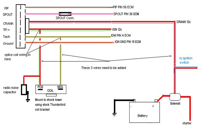
Here is a wiring diagram for the ignition system:
When you are done wiring this little section wrap the harness up with new
loom, and tape it up nice.
Note here I used the throttle body from the
91-93 engine to keep from having
to change any TPS wires. If you want to use the T-bird throttle body you
will have to change the connector. They are both the same size.
If you choose to use the turbo throttle body (one advantage is it has an
adjustable Throttle Position Sensor), here is what I've found as far as
wiring goes:
Turbo
TPS Plug/Stock 1991 Plug
From Top:
Orange------->Brown/White
Green-------->Grey/White
Red---------->Grey/Red
Be sure to mount the coil behind the battery with the factory mount from
the thunderbird.
Be sure
to remove the vacuum line from the factory 91-93 Mustang MAP sensor. This
makes it a BAP sensor which is what the turbo engine needs to run
properly. This sensor is what you ran orange/white VAM wire to at the
beginning of this article.
The Mustang oxygen sensor
can be used with the TC computer if you swap it into the turbo down elbow
where the factory sensor on the turbo engine resides. The turbo ECU is
set up for a 3 wire o2 sensor and the Mustang uses a 4 wire unit with
integral HEGO ground wire (hence the difference between the 3 wire 87-88
TC o2 sensor and the 4 wire Mustang o2 sensor). The Turbo Coupe has an
orange external ground wire that bolts to the turbo. If you want to run
the 87-88 TC o2 sensor, one of the alignment tabs will need to be removed
to get it to plug in. The 3 wires are in the proper locations, just make
sure you follow the instructions for pin 49 in the pinouts listing below
to account for the 4th o2 wire.
You will need to use the
fuel injector harness from the Mustang so you can plug it into the stock
harness. All the wires are correct. Make sure you don't use
the 91-93 Mustang injectors or fuel rail, they won't work.
Note that you will need
to move that ACT Sensor that was located in your airbox to somewhere after
the intercooler. The 87-88 intakes already have them in the back of
the lower intake. You will need to move/lengthen the wires to reach
the new location. I chose to mount mine in the IC tubing right
before the throttle body. If you're running a PiMP ECU or other
aftermarket ECU, it is best to mount the ACT in a location that's less
likely to heat soak when the engine is idling, or has been shut off
while hot. This would mean the upper intake is a better location than
the factory lower intake location, and in the intercooler tubing after
it leaves the intercooler but before it gets near the engine would be
ideal. This way the sensor outputs accurate air temp readings under all
conditions.
Also note I did not use the coolant temp sensor that is located in the
t-bird intake manifold, I kept it in the location it is in originally in
the Mustang (in the heater hose). You will need to do this as well to get the fan to function.
If
your base turbo engine is a 83-86 model you will need to rig up your own
fuel lines from the rail to the steel lines located near the bell housing.
The stock mustang ones will not work. The 87-88 cars hook right up
to the stock lines. I chose to cut the lines out of the turbo coupe
and then cut them to the length needed for the mustang. I then slid
the factory style connectors into the plastic fuel line (may need to
smooth out ends of connections with grinder and then lube to get them
inserted all the way) and then used two small hose clamps on each one to
keep them from leaking. If was the cheapest/quickest way I could find to fix
the problem.
Plastic fuel line repair kits are available from most parts stores that
allow you to make the lines just like they came from the factory without
using hose clamps. This is the best option.
If you want to have a functioning octane switch (a toggle switch that
modifies the timing map for premium and regular fuel), you'll need to
install a toggle switch and wire it so it grounds pin 24 to put it in
premium mode and removes the ground for regular mode.
Here
are the pinouts for the computer swap:
|
Pin 1 KAPWR
|
yellow
|
OK |
|
Pin
2 BOO
|
lt grn
|
OK |
|
Pin 3 VSS DIF+
|
gry/blk
|
OK |
|
Pin 4 IDM
|
tan/yel
|
OK |
|
Pin
5 CID
|
dk blu/or
|
Remove pin |
|
Pin 6 VSS DIF-
|
pnk/or
|
OK
|
|
Pin 7 ECT
|
lt grn/rd
|
OK |
|
Pin
8 FPM
|
dk grn/yel
|
Remove pin |
|
Pin
9 DATA-
|
pnk/lt blu
|
Remove pin |
|
Pin 10 ACCS
|
blk/yel
|
OK |
|
Pin
11
|
OK |
|
|
Pin
12
|
OK |
|
|
Pin
13
|
OK |
|
|
Pin 14 MAF
|
lt blu/rd
|
Remove pin and
install @pin 43 (Note 1) |
|
Pin 15 MAF RTN |
tan/lt blu
|
Remove pin and
install @pin 27 (Note 2) |
|
Pin 16 ign gnd
|
or/rd
|
OK |
|
Pin 17 STO/MIL
|
pink/lt grn
|
OK |
|
Pin
18
|
OK |
|
|
Pin
19
|
OK |
|
|
Pin 20 CASE GND
|
blk
|
OK |
|
Pin 21 ISC/BPA
|
wht/lt blu
|
OK |
|
Pin
22 FP
|
lt blu/or
|
OK |
|
Pin
23
|
pin in Knock Sensor
here |
(Optional) Only necessary if knock
sensor will be used |
|
Pin 24 PSPS
|
yel/lt grn
|
Cut wire and ground it to the chassis for premium
fuel only mode or ground this wire with a toggle switch for premium/regular
fuel switching manually. When grounded 91+ octane fuel is required. |
|
Pin
25 ACT
|
gry
|
OK |
|
Pin
26 5VREF
|
brn/wh
|
OK |
|
Pin 27 EVP
|
brn/lt grn
|
Remove pin
replace with pin moved from pin 15 (Note 2) |
|
Pin
28 DATA+
|
tan/or
|
Remove pin |
|
Pin 29 HEGO
|
gry/lt blu
|
OK |
|
Pin 30 NDS
|
lt blu/yel
|
OK |
|
Pin 31 CANP
|
gry/yel
|
Remove pin splice
in BCS if used (I use manual boost control instead) |
|
Pin
32 DPI
|
dk blu/yel
|
Remove pin |
|
Pin
33 EVR
|
brn/pnk
|
OK |
|
Pin
34
|
OK |
|
|
Pin
35
|
OK |
|
|
Pin
36 SPOUT
|
pnk |
OK |
|
Pin
37 12VPWR
|
red
|
OK |
|
Pin
38
|
OK |
|
|
Pin
39
|
OK |
|
|
Pin 40 PWR GND
|
blk
|
OK |
|
Pin
41
|
OK |
|
|
Pin
42
|
OK |
|
|
Pin
43
|
Install pin 14 here |
Install pin 14 here
(Note 1) |
|
Pin 44 OCT ADJ |
dk grn
|
Remove pin |
|
Pin
45 BP
|
lt grn/bk
|
OK |
|
Pin 46 SIG RTN
|
gry/rd
|
OK |
|
Pin 47 TP
|
gry/wh
|
OK |
|
Pin 48 STI
|
wht/ppl
|
OK |
|
Pin 49 HEGO
GND |
orange |
OK if running 4
wire o2 sensor, splice into
wire and run to turbo hot side for o2 sensor ground if running 3 wire
o2. |
|
Pin
50
|
OK |
|
|
Pin 51 EDF
|
lt grn/ppl
|
Move this to pin
55 for cooling fan function. (I opted to use only one speed cooling
fan) |
|
Pin
52 SS 3/4
|
org/yel
|
Remove pin |
|
Pin 53 CCO
|
ppl/yel
|
Remove pin |
|
Pin 54 WAC
|
pnk/yel
|
OK |
|
Pin
55
|
empty
|
|
|
Pin
56 PIP
|
gry/org
|
OK |
|
Pin
57 12VPWR
|
red
|
OK |
|
Pin 58 inj bank1
|
tan
|
OK |
|
Pin 59 inj bank2
|
wht
|
OK |
|
Pin 60 PWR GND
|
blk
|
OK |
© Stinger Performance Engineering 2020 |